Spin-to-charge conversion + rf reflectometry ro_s2c
Spin converted into a charge-motion event by Pauli spin blockade or energy-selective tunnelling, then read by an rf-matched charge sensor in microseconds without destroying the qubit.
Spin-to-charge conversion + rf reflectometry
Pauli/energy-selective tunnelling sensed by a gate-based single-electron box (SEB) or an SET; 99.2% in < 6 µs; 99.9% at 100 µs.
Brief →Key references
Design space — attributes
- (a) carrier affinity
- fabricated
- (b) time · entangling
- —
- (c) readout
- spin-to-charge + rf reflectometry · 6.3 µs · non-destructive · mid-circuit
- (d) mobility
- —
- (e) control
- low-frequency electrical @ room temperature
- (f) error structure
- coherent / calibration
- (g) manufacturing
- CMOS foundry 300 mm
Evaluation space — dated attributes
The 99.2% in < 6 µs is Oakes et al., PRX 13, 011023 (2023), Quantum Motion — an rf single-electron box, not an SET.
Standard records
Actors & goals — annotations
Edges
Used by 10 machines (10 primary · 0 alternate)
- semiconductor spins 10
- Diraq 8-qubit silicon spin quantum computer at Equinix Sydney Diraq (with Equinix) ◌ 🔎
- foundry 8-qubit array Diraq paper press ▣ Fig. 1b (direct SET vs cascaded spin-to-charge readout); §II.2 ✅
- RacQ (Bell-1) Equal1 product page blog blog ▦ UnityQ specifications ('Readout fidelity 99%', 'Parity readout') ✅
- Groove Quantum 18-qubit germanium spin processor Groove Quantum press ◌ 🔎
- Hitachi x Intel 18A spin programme Hitachi + Intel K.K. + AIST (G-QuAT) press press ◌ 🔎
- HRL exchange-only silicon spin processor (18 EO qubits from 54 quantum dots) HRL Laboratories (IBM since 26 Aug 2026) paper press ▤ Methods: Exchange-only qubits; SI S3.D; Fig. 1b ✅
- Tunnel Falls Intel paper press press ◌ 🔎
- QM-One Quantum Motion ▣ Fig. 1 (device and measurement setup); Fig. 2, Fig. 4 (spin readout fidelity); §II–III; §VI.B ✅
- Alloy Pioneer (Quobly) Quobly press ◌ 🔎
- 11-qubit donor processor Silicon Quantum Computing paper press ▤ §Main (QND readout of each nuclear spin via the ancillary electron); Fig. 1 (single-qubit characteristics) ✅
Pictures
Every picture carries the story of what it shows and its credit line.
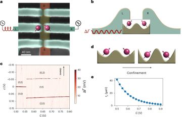
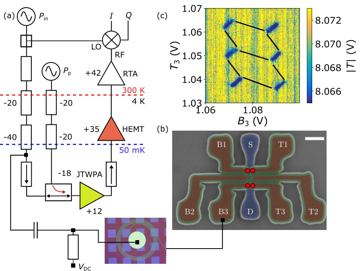
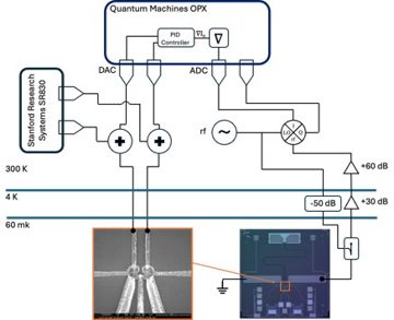
Spin-to-charge conversion + rf reflectometry
Spin converted into a charge-motion event by Pauli spin blockade or energy-selective tunnelling, then read by an rf-matched charge sensor in microseconds without destroying the qubit.
Verdict. The readout every silicon architecture uses and the term that sets the silicon clock — 6 µs at 99.2% or 100 µs at 99.9%, with no published device delivering both.
Λ = error-suppression factor per code-distance step; QBI = DARPA Quantum Benchmarking Initiative (Stage A concept → B R&D plan → C government V&V); G1–G7 = the report's goal classes (see Actors & economics).
Identity & lineage
Spin carries no charge, so a tunnelling event is made spin-conditional — Pauli spin blockade (PSB; two-spin parity, scale = singlet–triplet splitting) or energy-selective Elzerman tunnelling (single spin, needing Zeeman ≫ kT) — and a charge sensor reports it. The sensor is a single-electron transistor or a gate-based single-electron box read via quantum capacitance, in an LC (inductor–capacitor) tank near 0.1–2 GHz. Elzerman single-shot readout dates to 2004. Attributes: readout — spin-to-charge, ~6 µs, non-destructive, mid-circuit-capable; control — low-frequency drive from room temperature, sensor in CMOS, carrier immobile.
Physics & limits
Per-shot signal-to-noise is the phase shift integrated against amplifier noise over a window capped by T1 and floored by tank bandwidth — the whole trade: 99.2% under 6 µs D[624] against 99.9% SPAM at 100 µs D[189]. Elzerman readout dies as kT approaches the Zeeman energy, so hot (≈1 K) operation costs readout first; Pauli spin blockade survives there but answers parity. Relaxation inside the window returns a false ground state, and sensor charge noise walks the threshold, so measurement error is drifting and correlated, not independent as decoders assume. Quantum-limited amplification and in-fridge demodulation move the floor.
Engineering state of the art
table
| year | figure | who | tag+key |
|---|---|---|---|
| 2023-02-23 | 99.2% single-shot in <6 µs, rf single-electron box | Quantum Motion | D[624] |
| 2025-09-24 | 99.9% SPAM at 100 µs, 300 mm SiMOS | Diraq | D[189] |
Dominant term: SNR at short windows, T1 at long; no foundry device publishes sub-10 µs readout above 99.5%.
The ZQCS channel count is a trade-press restatement of a vendor launch, not a primary release. Not published: a readout-only fidelity, separated by randomised benchmarking, behind the Diraq/imec 99.9% quoted as SPAM.
Manufacturing, materials & supply chain
Built in the qubit's own 300 mm CMOS stack, the sensor adds no materials risk; the gate-based box, needing only an electrode and a tank, is the foundry-favoured form. Instrumentation is bought, not built: Zurich Instruments' SHFQC-LRT gives ≤32 µs weighted integration C[625], and Quantum Machines' OPX1000 lists nine spin customers including Diraq, HRL, imec and Equal1 C[449]. Frequency multiplexing keeps line count sub-linear: the wall at 10³ is tank spacing across the band; at 10⁴–10⁶ it is aggregate readout bandwidth and amplifier count, not the sensor. HRL's 4 K controller (366 DACs, ≤3.5 W) shows the chain can move inside the fridge D[190].
Role in the stack
Required by quantum-dot and donor spins, with no replace or conflict edges — the load-bearing readout node in both the silicon/germanium quantum-dot spin architecture and the donor-spin architecture. The register lists 10 machines using it, among them QM-One, RacQ (Bell-1), the 11-qubit donor processor and the HRL exchange-only silicon spin processor (18 EO qubits from 54 quantum dots). With exchange gates in tens of nanoseconds, readout at 6–100 µs sets derived clock = sum of the syndrome round: gate layers + transport + readout + reset: 8.5×10⁻⁶ s at the fast end, 6.3 µs of it readout. Verification: the two headline figures are different devices with different sensors — a speed–fidelity curve, not one system — and the 99.9% bundles initialisation. Neither is replicated independently.
Actors & economics
Who.
| Organisation | Role | Country | What they do | Evidence |
|---|---|---|---|---|
| Quantum Motion | developer | UK | Single-electron-box readout, 99.2% in <6 µs | D[624] |
| Diraq | developer | Australia | 99.9% SPAM on 300 mm imec SiMOS | D[189] |
| Silicon Quantum Computing | developer | Australia | Readout of donor nuclear registers | Dfact |
| HRL Laboratories | developer | USA | Readout sequenced by 4 K cryo-CMOS | Dfact |
| Zurich Instruments | supplier | Switzerland | Sells the reflectometry instruments | C[625] |
| Quantum Machines | supplier | Israel | Readout stack for nine spin teams | C[449] |
Money. 2025-02-25 · Quantum Machines · Series C · $170 M · PSG Equity, Intel Capital · closed Cfact. 2025-11-06 · Diraq, Quantum Motion, SQC · QBI Stage B · ≤$15 M each · DARPA · selected fact. 2026-05-07 · Quantum Motion · Series C · $160 M · DCVC, Kembara · closed Cfact. 2026-05-21 · Diraq · CHIPS LOI · ≤$38 M · US Commerce · non-binding fact.
Market & supply chain. Zurich Instruments and Quantum Machines supply the rf chain nearly every spin team buys rather than builds C[449], [625]; cryogenic amplification is the second pinch point. Pays into G2, G3, G7.
IP & standards. No dated patent family for spin-to-charge conversion or rf reflectometry in a named database as of 4 Sep 2026.
Roadmaps & track record. Diraq (2026-08-27 · 150 k physical, 1 k logical by 2029 · unmet; its 2026-07-09 release said "thousands by 2029") Rfact. Zurich Instruments (2026-03-09 · ZQCS for "several thousand qubits" · shipping) P[526]. No vendor promises a dated readout rate; instruments ship on schedule, qubit counts do not.
Strategic reading. Readout is the one silicon subsystem bought rather than built, so control-electronics vendors keep leverage whichever qubit wins; if the gate-based box displaces the sensor transistor, the foundry captures it and per-qubit-sensor designs lose twice.
Outlook & open questions
Confirm or demote in 12–24 months: ≥99.9% below 20 µs on a foundry device; ≥16 sensors multiplexed on one line with a crosstalk number. Best case 2029: >100 sensors read under 10 µs each, demodulated in-fridge. Worst case: readout stays the clock-setting term and the largest syndrome-cycle error. Open: (1) tanks per quantum-limited amplifier; (2) whether parity readout suffices without a per-qubit ancilla; (3) how correlated threshold drift looks to a decoder.
References
- [189] P. Steinacker et al., “Industry-compatible silicon spin-qubit unit cells exceeding 99% fidelity,” Nature, vol. 646, no. 8083, pp. 81–87, Sep. 2025, doi: 10.1038/s41586-025-09531-9. D
- [190] Members of the HRL Quantum Team and Collaborators, “A digitally controlled silicon quantum processing unit,” arXiv:2604.16216, Apr. 2026. D
- [449] Quantum Machines, “Semiconductor Spin Qubits,” Aug. 11, 2026. [Online]. Available: https://www.quantum-machines.co/
qubit-types/ Csemiconductor-spin-qubits/ - [526] Zurich Instruments, “Zurich Instruments Launches the ZQCS Quantum Control System to Master the Long-Lived Logical Qubit Challenge,” Mar. 9, 2026. [Online]. Available: https://www.zhinst.com/
americas/ Pen/ news/ zurich-instruments-launches-zqcs-quantum-control-system-master-long-lived-logical-qubit/ - [624] G. A. Oakes et al., “Fast High-Fidelity Single-Shot Readout of Spins in Silicon Using a Single-Electron Box,” Phys. Rev. X, vol. 13, no. 1, Art. no. 011023, Feb. 2023, doi: 10.1103/PhysRevX.13.011023. D
- [625] Zurich Instruments, “SHFQC-LRT Long Readout Time,” Jan. 30, 2025. [Online]. Available: https://www.zhinst.com/
en/ Cproducts/ shfqc-lrt-long-readout-time