rf quantum-capacitance parity readout ro_qcap
Dispersive gate sensing of a Majorana island's quantum capacitance by rf reflectometry, reading fermion parity without charge transfer; non-destructive and mid-circuit.
rf quantum-capacitance parity readout
Interferometric parity readout of a Majorana wire; 1% assignment error, SNR 1 in 3.6 µs.
Brief →Key references
Design space — attributes
- (a) carrier affinity
- fabricated
- (b) time · entangling
- —
- (c) readout
- rf quantum capacitance (parity) · 100 µs · non-destructive · mid-circuit
- (d) mobility
- —
- (e) control
- low-frequency electrical @ room temperature
- (f) error structure
- unknown / contested
- (g) manufacturing
- III-V MBE heterostructures
Evaluation space — dated attributes
The independent replication is van Loo et al., Nature 650 (2026-02-11), on an InSb minimal Kitaev chain; arXiv:2607.09511 is the follow-on coherent parity qubit, a different result.
Standard records
Actors & goals — annotations
Edges
Used by 2 machines (2 primary · 0 alternate)
- topological 2
- Majorana 1 Microsoft paper press ▣ Fig. 1 (TQDI dispersive gate-sensing loop); Fig. 3 (parity measurement A1); Fig. 4 (simulated CQ) ✅
- Majorana 2 Microsoft blog blog press ▤ Abstract ✅
Pictures
Every picture carries the story of what it shows and its credit line.
rf quantum-capacitance parity readout
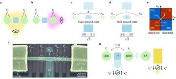
Dispersive gate sensing of a Majorana island's quantum capacitance by rf reflectometry, reading fermion parity without charge transfer; non-destructive and mid-circuit.
Verdict. The method is real and independently replicated; falsified as fault-tolerance-grade unless an assignment error below 10⁻³ at a stated integration time is published by 2028, on any stack.
Λ = error-suppression factor per code-distance step; QBI = DARPA Quantum Benchmarking Initiative (Stage A concept → B R&D plan → C government V&V); G1–G7 = the report's goal classes (see Actors & economics).
Identity & lineage
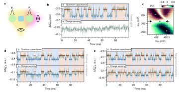
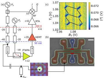
A dot–nanowire interference loop's ground state disperses differently with gate charge in the two parity sectors; that curvature is a quantum capacitance, read as a dispersive shift of an off-chip resonator by rf reflectometry, with no charge transfer. Microsoft, Nature 2025-02-19: 1% assignment error, SNR 1 in 3.6 µs, dwell above 1 ms near 2 T D[13]. This is the single-wire (Z-type) measurement; the joint projection a gate needs is unbuilt.
a fabricated (1.0) · b not a gate · c quantum capacitance, ~4 µs, non-destructive, mid-circuit
d no transport · e rf reflectometry from room temperature · f assignment error plus poisoning · g MBE wire stack
Physics & limits
Signal accumulates as √t while parity survives only until a quasiparticle arrives, so assignment error is a race, modelled as err ≈ ½[1 − e^(−2t/τ)·erf(SNR/√2)²] at mean SNR near 1.2 per µs D[20]. The floor is the poisoning time τ, set by loop geometry, not the amplifier: the same device gives 12.4 ms on the Z loop against 14.5 µs on the X loop, attributed to the two-loop configuration's larger quasiparticle-capture cross-section D[20]. Lead replaced aluminium to raise τ D[21]. What it reads is contested: Nature's editor's note says the results do not by themselves establish Majorana zero modes P[214].
Engineering state of the art
table
| Year | Figure | Who | Tag+key |
|---|---|---|---|
| 2025-02 | 1% assignment error, SNR 1 in 3.6 µs, dwell >1 ms, InAs–Al | Microsoft Azure Quantum | D[13] |
| 2026-02 | Independent single-shot parity readout, ~1.85 ms switching, InSb Kitaev chain | QuTech | D[216] |
| 2026-06 | ~20 s parity switching in one InAs–Pb wire, same readout family | Microsoft Quantum | D[21] |
Typical at scale is undefined: no multiplexed multi-tetron readout is published; the 2026 device came up one wire at a time D[21].
The arXiv full text of [20] also gives X ~4 µs and Z ~9.3 ms for other tunings, against the 14.5 µs / 12.4 ms used here. The quasiparticle-poisoning rate during a readout dwell has only been inferred, never measured directly. Not published: a readout-specific R&D spend.
Manufacturing, materials & supply chain
No dedicated process: dots, gates and loop share the wire device's lithography, resonator off-chip. Room-temperature rf drive and demodulation feed a millikelvin amplifier, from the merchant control-electronics base superconducting readout uses Cfact; no single point of failure beyond the wire stack, and no export-control category specific to it. I/O is a gate line and a resonator per measurable parity, multiplexed on a shared feedline: 10³ is solved packaging. The wall is time: 3.6 µs is fast against 12.4 ms, slow against 14.5 µs, so at 10⁴–10⁶ the limit is how many X projections fit in the shorter window.
Role in the stack
The one demonstrated block the topological architecture owns: it requires the Majorana-parity carrier and provides the projective measurement a measurement-based gate would consume, non-destructively and mid-circuit, the precondition for measurement-only architecture. It is the only defined term of the architecture's derived clock: in sum of the syndrome round: gate layers + transport + readout + reset only readout is published, ~3.6 µs to SNR 1 D[13], with no code and no reset figure. Verification: QuTech's Nature paper (2026-02-11) independently replicates the principle on InSb dot-based Kitaev chains rather than a tetron, at ~1.85 ms telegraph lifetimes D[216]; its follow-up shows coherent parity oscillations with only limited protection D[217]. Legg disputes whether the read regions are gapped at all D[22]. Nobody has replicated the 1% error.
Actors & economics
Who.
| Organisation | Role | Country | What they do | Evidence |
|---|---|---|---|---|
| Microsoft Quantum | developer | US | Originated the method; used on every tetron device | D[13] |
| QuTech | research | NL | Independent parity readout and coherent parity qubit, on Eindhoven-grown InSb wires | D[216] |
| DARPA | investor | US | Funds the only industrial user; US2QC final stage since 2025-02-06 | fact |
Money. 2025-02-06 · Microsoft · US2QC final Validation & Co-Design stage · undisclosed · DARPA · announced fact. 2026-01-23 · Microsoft · Quantum Pioneers Program, readout an award topic · ≤ USD 200,000 per proposal · announced Pfact.
Market & supply chain. No standalone market; rf reflectometry and cryogenic amplification are generic and multi-sourced, so concentration risk sits in the wire stack. G3 and G4 only.
IP & standards. Dispersive gate sensing is common property across semiconductor-qubit groups; no dated patent count specific to parity readout as of 4 Sep 2026.
Roadmaps & track record. (used in every public Microsoft device from 2025-02, implicitly for fault tolerance by 2029; status 4 Sep 2026: no fidelity or speed target published for the readout) C[215]. QuTech publishes with no schedule to defend, the more credible record.
Strategic reading. The method is public and replicated, so Microsoft's exclusivity has moved into the wire stack; whoever first publishes assignment error near 10⁻³ at a stated integration time sets the downstream pace.
Outlook & open questions
Falsifiable in 12–24 months: a third group publishing parity readout; a sub-1% assignment error from anyone but Microsoft; a directly measured poisoning rate. Confirm if two land; demote if it stays a two-laboratory result to 2028. Best case, readout stops being the open variable; worst case, τ on a joint loop stays in tens of µs. Open: does multiplexed multi-tetron readout work; is 1% reproducible off Microsoft's devices.
References
- [13] Microsoft Azure Quantum, “Interferometric single-shot parity measurement in InAs–Al hybrid devices,” Nature, vol. 638, no. 8051, pp. 651–655, Feb. 2025, doi: 10.1038/s41586-024-08445-2. D
- [20] M. Aghaee et al., “Distinct Lifetimes for X and Z Loop Measurements in a Majorana Tetron Device,” arXiv:2507.08795, Jul. 2025. D
- [21] M. Aghaee et al., “20 Second Parity Lifetime in an InAs–Pb Tetron Device,” arXiv:2606.03884, Jun. 2026. D
- [22] H. F. Legg, “On the robustness of topological gap detection via transport,” Nature, vol. 654, no. 8120, pp. E22–E26, Jun. 2026, doi: 10.1038/s41586-026-10567-8. arXiv:2503.08944. D
- [214] P. Ball, “Experts Weigh in on Microsoft's Topological Qubit Claim,” Physics, vol. 18, p. 57, 2025. [Online]. Available: https://physics.aps.org/
articles/ Pv18/ 57 - [215] C. Nayak, “Majorana 2 – Microsoft's Scalable Quantum Processor With Reliable, Long-Lasting Qubits,” Microsoft Quantum. [Online]. Available: https://quantum.microsoft.com/
en-us/ Cinsights/ blogs/ majorana-2-scalable-quantum-processor - [216] N. van Loo et al., “Single-shot parity readout of a minimal Kitaev chain,” Nature, vol. 650, no. 8101, pp. 334–339, Feb. 2026, doi: 10.1038/s41586-025-09927-7. D
- [217] F. Zatelli et al., “Majorana parity qubit in coupled minimal Kitaev chains,” arXiv:2607.09511, Jul. 2026. D