← Quantum Technology AtlasTechnologies · Machines · Architectures · OrganisationsРусскийעברית

11-qubit donor processor

Silicon Quantum Computing

11-qubit donor processor

Silicon Quantum Computing · semiconductor spins · DEMONSTRATED (Dec 2025 (Nature 648, 569; SQC release 18 Dec 2025)) · 11 physical qubits · access: lab-only

Register profile — the machine's variant of its architecture

qubit type: P-31 donor nuclear spins in isotopically purified Si-28, STM-placed to a stated 0.13 nm accuracy (not in the cited page)
gate mechanism: hyperfine-conditional rotations through a shared electron; exchange-based CROT in 1.25 us enabling non-local entanglement within a register
connectivity: register-local all-to-all through the shared electron; nearest neighbour between registers
control: baseband + ESR/NMR from room temperature
control placement: room-temp baseband
readout: QND readout via the electron spin - the only genuinely QND single-shot readout in this register
gate evidence: a benchmark paper with its protocol
flags: no foundry route

Technologies by layer — the machine's cell per layer

1 Qubit carrier
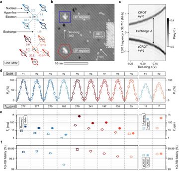
Donor spin (P in ²⁸Si) · primary ▣ Fig. 1b (STM micrograph of processor core: 4P register n1–n4/e1, 5P register n5–n9/e2) ✅
11 qubits: P-31 donor nuclear spins (data) in isotopically purified Si-28, STM-placed to 0.13 nm; shared electrons as ancillas; two registers of 4 and 5 nuclei (Nature, 4 Feb 2026)
2 Encoding
Single-spin (Loss–DiVincenzo) / nuclear-spin encoding · primary ▣ Fig. 1 (single-qubit characteristics of the 11-qubit atom processor) ✅
bare nuclear spin-1/2 of each P-31 donor as data qubit, electron spin as ancilla; no machine-specific encoding source
3 Gate mechanism
Exchange gate (spins; incl. shuttled-spin CZ) · primary ▣ Fig. 2 (two-qubit operation: nuclear CZ and electron CROT); Methods: Randomized benchmarking ✅
hyperfine-conditional rotations via shared electron; exchange-based electron CROT 1.25 µs, 99.64%; 1Q up to 99.99%; GHZ up to 8 nuclear spins (Feb 2026)
4 Connectivity / transport
Static nearest-neighbour lattice · primary ▣ Fig. 1a (connectivity of n1–n9 and e1–e2 via hyperfine and exchange coupling); Fig. 3 (local vs non-local Bell states) ✅
register-local all-to-all through the shared electron; nearest neighbour between the two registers (4 and 5 nuclei)
5 Control
Baseband electrical control (spins, Majorana) · primary ▤ Methods: Experimental set-up 🔎
baseband + ESR/NMR from room temperature
6 Readout
Spin-to-charge conversion + rf reflectometry · primary ▤ §Main (QND readout of each nuclear spin via the ancillary electron); Fig. 1 (single-qubit characteristics) ✅
QND single-shot readout of the nuclear spins via the electron spin
7 Code
— none — nothing in this layer ▨ 🔎
no code, no logical result; NISQ device
8 Decoder
— none — nothing in this layer ▨ 🔎
no decoder (no code run)
9 Interconnect
— none — nothing in this layer ◌ 🔎
none
10 Manufacturing
STM hydrogen-resist lithography (donors) · primary ▣ Fig. 1b (STM micrograph after hydrogen lithography); §Main (P atoms placed ≲3 nm apart) ✅
STM hydrogen lithography: serial, bespoke, no foundry route; SkyWater partnership for US manufacturing

Standard records

T2 coherence (echo/DD) → 660 ms · best (nuclear-spin Hahn echo)
Feb 2026 · source
evidence: ✅ 6 / 10

Pictures

Every picture carries the story of what it shows and its credit line.
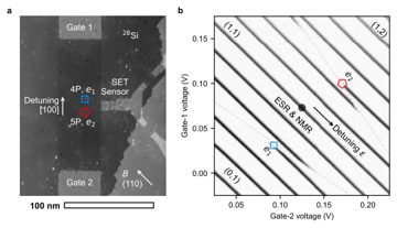
Fig. 5 — Figure S1: Basic operation of the 11-qubit atom processor via detuning gates. a, Scanning tunneling micrograph showing the core of the atom processo…
A two-panel figure. (a) A real scanning tunnelling micrograph (100 nm scale bar) of the processor core on silicon-28: two patterned gates, a single-electron-transistor (SET) charge sensor and the sites of two donor registers, 4P and 5P (four and five phosphorus atoms), each with one electron (e1, e2); (b) a measured charge-stability map versus the two gate voltages, with charge states, a detuning axis ε and the working point where an antenna drives electron and nuclear spin resonance (ESR, NMR). It is Figure S1 of 'An 11-qubit atom processor in silicon' by Hermann Edlbauer and co-authors. Gate voltages set the electron charge states of these atomically placed donors. “Fig. 5 — Figure S1: Basic operation of the 11-qubit atom processor via detuning gates. a, Scanning tunneling micrograph showing the core of the atom processor with the…” by Hermann Edlbauer et al., arxiv.org/abs/2506.03567, CC BY 4.0 (creativecommons.org/licenses/by/4.0/)
Fig. 1 — Figure 1: Single-qubit characteristics of the 11-qubit atom processor. a, Connectivity of nuclear spins (n1n-n9n) and electron spins (e1e and e2e_{2
A six-panel figure: (a) a drawn connectivity graph of nine nuclear spins and two electron spins; (b) a scanning tunnelling micrograph of a silicon surface, with 10 nm scale bar, showing the patterned 4P and 5P donor registers and a single-electron-transistor sensor; (c)–(f) spectroscopy and plots of Rabi oscillations, coherence times and single-qubit benchmarking fidelities. It is Figure 1 of "An 11-qubit atom processor in silicon" by Edlbauer, Wang, Huq and co-authors. Notice the visible atomic rows: phosphorus donors are placed by hydrogen lithography with near-atomic precision. “Fig. 1 — Figure 1: Single-qubit characteristics of the 11-qubit atom processor. a, Connectivity of nuclear spins (n1n-n9n) and electron spins (e1e and…” by Hermann Edlbauer et al., arxiv.org/abs/2506.03567, CC BY 4.0 (creativecommons.org/licenses/by/4.0/)
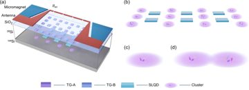
Fig. 1 — Figure 1: Physical schematic diagram of a quantum processor based on the donor cluster scheme. (a) The donor cluster array is positioned in the 28Si…
A 3D concept render, not a photograph: a layered silicon device with glowing donor clusters in an isotopically pure silicon-28 layer, top gates, single-lead quantum dots, a stripline antenna and micromagnets. It comes from Zhang, Hu, Zhang, Wang, Xin, He and Huang, paper "Scalable Spin Qubit Architecture with Donor-Cluster Arrays in Silicon". It illustrates a proposed architecture in which several donor nuclei share one bound electron whose spin carries the qubit; notice the electron "clouds" and the red antenna that drives spin resonance. “Fig. 1 — Figure 1: Physical schematic diagram of a quantum processor based on the donor cluster scheme. (a) The donor cluster array is positioned in the 28Si layer on…” by Shihang Zhang et al., arxiv.org/abs/2509.24749, CC BY 4.0 (creativecommons.org/licenses/by/4.0/)