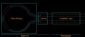
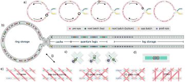
A fluorescence camera image of 98 trapped barium-137 ions lit by resonant laser light, with thin outlines drawn over it: a square 'Ring Storage' holding a ring of bright dots (each dot is one ion), a 'Cache' where two lines cross, and a long 'Quantum Logic' region. It is Fig. 1 of an arXiv paper by A. Ransford et al. (Quantinuum), dated 2025-11-07, showing the Helios 2D surface trap. Notice how memory (ring and cache) is kept apart from the processor zone; ions are shuttled between them through a junction.“Fig. 1 — 98 atomic ions illuminated by resonant laser light in the Helios 2D surface trap” by Ransford, A. et al. (Quantinuum), arxiv.org/abs/2511.05465, CC BY 4.0 (creativecommons.org/licenses/by/4.0/)Fig. 1 — A picture of the H2 surface ion trap microchipתמונה חיצונית — נפתחת במקורAn oblique photograph of the square H2 surface ion-trap die: bond pads line the edges and long electrode rails lead to an oval 'racetrack' electrode structure in the centre. Fig. 1 of Moses et al. (Quantinuum), 'A Race Track Trapped-Ion Quantum Processor', arXiv 2305.03828 (2023-05-05); the caption says the image was modified to enhance trap features, so the rainbow colours are not real. Ions float just above these electrodes and are moved around the racetrack by changing electrode voltages, the basis of ion shuttling.A multi-panel schematic drawing: (a) rings of coloured ion dots showing loading in batches, (b) the trap layout, a ring-shaped storage region joined through an X-shaped junction to a cache, a quantum-logic region and leg storage, (c) close-ups of ions crossing the junction, (d) an aligned ion pair, (e) crossed laser-beam layouts. It is Fig. 2 of an arXiv paper by A. Ransford et al. (Quantinuum), dated 2025-11-07, on the Helios design and operations. Follow the ions from storage through the junction to the lasers.“Fig. 2 — Illustration of the Helios design and conception of operations” by Ransford, A. et al. (Quantinuum), arxiv.org/abs/2511.05465, CC BY 4.0 (creativecommons.org/licenses/by/4.0/)