← Quantum Technology AtlasTechnologies · Machines · Architectures · OrganisationsРусскийעברית

Zuchongzhi 3.0

USTC / Hefei National Laboratory

Zuchongzhi 3.0

USTC / Hefei National Laboratory · superconducting circuits · DEMONSTRATED (Dec 2024 / Mar 2025) · 105 physical qubits · access: lab + Tianyan cloud sibling

Register profile — the machine's variant of its architecture

qubit type: tunable transmon, tantalum-aluminium on sapphire
gate mechanism: tunable coupler CZ-family; 1Q 28 ns, 2Q 45 ns
connectivity: rectangular lattice, average connectivity 3.5
control: room-temperature RF
control placement: room-temp
readout: dispersive
gate evidence: a number stated by the vendor, protocol unstated
flags: estimated baseline

Technologies by layer — the machine's cell per layer

1 Qubit carrier
Transmon · primary ▣ Fig. 1a (flip-chip device, 105 qubits); §II ✅
tunable transmon, tantalum–aluminium on sapphire; 105 readable qubits; T1 ≈72 µs, T2 ≈58 µs (averages, Mar 2025)
2 Encoding
Bare physical qubit (no encoding) · primary ◌ 🔎
Bare two-level subspace — Computational subspace of an anharmonic oscillator; leakage to |2⟩ is the price.
3 Gate mechanism
Tunable-coupler CZ / iSWAP · primary ▣ Fig. 1c (two qubits via coupler); §II ✅
tunable couplers (182), CZ-family; 1Q ≈28 ns, 2Q ≈45 ns; parallel 1Q 99.90%, 2Q 99.62% (Mar 2025)
4 Connectivity / transport
Static nearest-neighbour lattice · primary ▣ Fig. 1b (qubit/coupler topology) ✅
15×7 rectangular lattice with 182 tunable couplers; average connectivity ≈3.5
5 Control
Room-temperature electronics + per-qubit coax/flex · primary ▣ Fig. 1a (control lines on second chip); §II (wiring attenuators) ✅
room-temperature RF
6 Readout
Dispersive microwave readout (+TWPA, Purcell) · primary ▣ Fig. 1a (readout resonators on second chip); §II ✅
dispersive; readout 99.18% (arXiv) / 99.13% (USTC release), sources conflict
7 Code
— none — nothing in this layer ▤ §III (large-scale random circuit sampling) ✅
no QEC code run on 3.0 (NISQ); RCS 83 q × 32 cycles, 10⁶ samples in a few hundred seconds; surface-code d=7 work stated separately
8 Decoder
— none — nothing in this layer ▤ 🔎
no decoder (no QEC on 3.0)
9 Interconnect
Multi-die packaging in one module (flip-chip, bump-bonded control die) · primary ▣ Fig. 1a (two sapphire chips, flip-chip) ✅
flip-chip: two chips bonded face-to-face, separating qubit layer from routing; one module, no inter-module interconnect
10 Manufacturing
Superconducting-qubit lithography (Al/AlOx/Al junctions, Nb wiring, 300 mm) · primary ▤ §II (fabrication procedure) ✅
Superconducting-qubit lithography (Nb/Al JJ, 300 mm) — IBM Albany 300 mm / Anderon foundry; Google Santa Barbara; Rigetti ABAA trimming (97.4% frequency-targeting success); OQC 500-qubit wafer-scale…

Standard records

connectivity degree → 3.5 neighbours · typical (mean)
Mar 2025 · source
2Q error under full-width parallel operation → 3.80e-3 · typical (99.62% parallel 2Q)
Mar 2025 · source
SPAM error → 8.20e-3 · typical (readout error; sources give 8.2e-3 and 8.7e-3)
Mar 2025 · source
T1 relaxation → 72 µs · typical
Mar 2025 · source
1Q gate time → 28 ns · best
Mar 2025 · source
T2 coherence (echo/DD) → 58 µs · typical
Mar 2025 · source
evidence: ✅ 8 / 10

Pictures

Every picture carries the story of what it shows and its credit line.
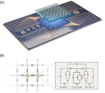
Fig. 1 — Device schematic of the Zuchongzhi quantum processor (two sapphire chips; 66 qubits and 110 couplers)
A paper figure, drawn rather than photographed: (a) a 3D render of a flip-chip processor, a translucent sapphire qubit chip floating above a larger wiring chip marked with Chinese characters; (b) a grid of cross-shaped qubits with coupler bars and a two-qubit-plus-coupler circuit. Fig. 1 of Yulin Wu, Wan-Su Bao et al., arXiv 2106.14734 (2021-06-28), showing the Zuchongzhi processor: two sapphire chips, 66 qubits and 110 couplers. Notice that every pair of neighbouring transmons is linked through its own tunable coupler. “Fig. 1 — Device schematic of the Zuchongzhi quantum processor (two sapphire chips; 66 qubits and 110 couplers)” by Yulin Wu, Wan-Su Bao, Sirui Cao, Fusheng Chen, Ming-Cheng Chen, et al., arxiv.org/abs/2106.14734, CC BY 4.0 (creativecommons.org/licenses/by/4.0/)
Fig. 1 — Zuchongzhi 3.0 quantum processor (a: illustration of flip-chip two-sapphire-chip device; b: qubit/coupler topology; c: simplified circuit schematic) external image — opens at the source
A three-panel paper figure of drawings, not photographs: (a) a rendered exploded view of the flip-chip, two-sapphire-chip processor; (b) a lattice map of qubits joined by coupler links; (c) a circuit schematic of two qubits and a tunable coupler. It is Fig. 1 of arXiv 2412.11924 by Dongxin Gao, Daojin Fan, Chen Zha and colleagues (December 2024) on the 105-qubit Zuchongzhi 3.0. In (c), each transmon and the coupler contain SQUIDs; tuning the coupler turns neighbour interactions on and off for two-qubit gates.
Fig. 2 — single-qubit (a) and two-qubit (b) gate error rates of Zuchongzhi 3.0 external image — opens at the source
Three colour heat maps drawn on the layout of the 105-qubit Zuchongzhi 3.0 superconducting processor, each tile printing its measured error: single-qubit gates (average 0.97 per thousand), two-qubit gates on the couplers (average 3.75 per thousand) and readout (average 8.67 per thousand). From Dongxin Gao, Daojin Fan and colleagues (arXiv, December 2024). Notice that errors differ from qubit to qubit, that grey tiles are unused, and that readout, not the gates, is the weakest step.