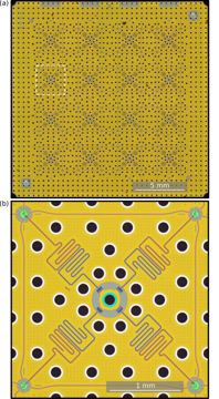
RIKEN 64-qubit superconducting processor
RIKEN with AIST, NICT, Osaka University, Fujitsu, NTT
RIKEN 64-qubit superconducting processor
Register profile — the machine's variant of its architecture
qubit type: transmon
gate mechanism: coupler type not published (fixed vs tunable unresolved)
connectivity: 2-D square arrangement of unit cells
control: microwave drive at 8-9 GHz; perpendicular ("3-D vertical") wiring package
control placement: room-temp
readout: dispersive
gate evidence: no published figure
flags: no published error rates, source not confirmed
Technologies by layer — the machine's cell per layer
| 1 Qubit carrier | |
| 2 Encoding | Bare physical qubit (no encoding) · primary ◌ 🔎 Bare two-level subspace — Computational subspace of an anharmonic oscillator; leakage to |2⟩ is the price. |
| 3 Gate mechanism | Tunable-coupler CZ / iSWAP · alternate ▨ 🔎 coupler type not published (fixed vs tunable unresolved); g_tc is nearest technology — undisclosed — exists, nothing published ▨ 🔎 gate mechanism not published; no official source states fixed capacitive vs tunable coupling |
| 4 Connectivity / transport | Static nearest-neighbour lattice · primary ▥ Fig. 1 (16 basic units of 4 qubits arrayed in a square); Fig. 6 (periodic planar tiling of 4-qubit units) ✅ 16 four-qubit unit cells in a 2-D square arrangement on one ~2 cm chip (64 q) |
| 5 Control | Vertical (out-of-plane) signal delivery — VIO, coaxmon, 3D wiring · primary ▥ Fig. 2 (perpendicular wiring package: control/readout lines via contact probes); Fig. 5 (wiring in DR) ✅ perpendicular ("3-D vertical") wiring package: signals brought in normal to the chip plane, not routed laterally; reused by Fujitsu at 256 q Room-temperature electronics + per-qubit coax/flex · alternate ▥ Fig. 3 (qubit controller: microwave oscillator + receiver; 96 input / 16 output wires) ✅ room-temperature microwave drive at 8–9 GHz into a dilution refrigerator |
| 6 Readout | Dispersive microwave readout (+TWPA, Purcell) · primary ▥ Fig. 3 (16 output wires for readout, microwave receiver); Fig. 2 (readout wiring) ✅ dispersive |
| 7 Code | |
| 8 Decoder | |
| 9 Interconnect | — none — nothing in this layer ▥ Fig. 1 (single 64-qubit chip); Fig. 5 (one chip in central magnetic shield) ✅ monolithic single ~2 cm chip, no interconnect |
| 10 Manufacturing |
evidence: ✅ 6 / 12
Pictures
Every picture carries the story of what it shows and its credit line.