Flux readout via QFP / SQUID shift registers (annealers) ro_fluxro
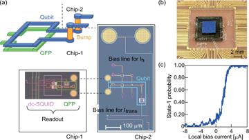
At the end of an anneal each flux qubit's persistent-current state is latched by a quantum flux parametron and carried as a classical bit to a detector — a dc SQUID, or on Advantage a frequency-multiplexed microresonator at the chip perimeter; no qubit is coupled to a readout resonator.
Flux readout via QFP / SQUID shift registers (annealers)
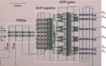
The annealer's own readout: the final flux state of each qubit is latched by a quantum-flux-parametron and clocked out through on-chip shift registers to a handful of lines — thousands of qubits read per anneal; no qubit is coupled to a resonator (the shift registers end in frequency-multiplexed microresonators at the chip edge).
Brief →Key references
Design space — attributes
- (a) carrier affinity
- fabricated
- (b) time · entangling
- —
- (c) readout
- flux latch (QFP/SQUID) · 100 µs · destructive · no mid-circuit
- (d) mobility
- —
- (e) control
- low-frequency electrical @ millikelvin stage
- (f) error structure
- stochastic Pauli
- (g) manufacturing
- superconducting lithography
Evaluation space — dated attributes
no dated attribute
A read of the whole chip takes 17–235 µs and ends the sample; it is not a mid-circuit measurement.
Actors & goals — annotations
Edges
Used by 3 machines (3 primary · 0 alternate)
- quantum annealers 3
- Advantage D-Wave Quantum docs ▤ §readout (QFP shift register; microresonator frequency multiplexing) ✅
- Advantage2 D-Wave Quantum paper docs docs ▦ §Advantage2_system1 (readout time range; readout error rate) 🔎
- Advantage3 D-Wave Quantum press link ◌ 🔎
Pictures
Every picture carries the story of what it shows and its credit line.

Flux readout via QFP / SQUID shift registers (annealers)
At the end of an anneal each flux qubit's persistent-current state is latched by a quantum flux parametron and carried as a classical bit to a detector — a dc SQUID, or on Advantage a frequency-multiplexed microresonator at the chip perimeter; no qubit is coupled to a readout resonator.
Verdict. Mature for its one job — 17–101 µs per read and ≤10⁻³ error per qubit on Advantage2, by D-Wave's own figures — but terminal by construction: as of 2026-09-26 no annealer reads mid-schedule, and no published Advantage2 readout architecture or readout-error method was found.
QFP = quantum flux parametron, an rf-SQUID flux latch; dc SQUID = two-junction interferometer used as a switching detector; Φ-DAC = on-chip flux digital-to-analogue converter; FASTR = flux-sensitive superconducting microresonator; CSFQ = capacitively shunted flux qubit; G1–G7 = the report's goal classes (see Actors & economics).
Identity & lineage
An annealer needs one measurement, in one basis, once. At the end of the schedule the tunnelling term A(s) is negligible and every rf-SQUID flux qubit has localised into one of two persistent-current states C[607]; the technology reads that classical flux. A QFP coupled to each qubit latches its sign, with flux sensitivity well beyond what a practical mutual inductance to a dc SQUID gives D[608]. The lineage is D-Wave's: a "robust and scalable" rf-SQUID qubit D[609], a 128-qubit latch-plus-dc-SQUID readout D[608], and on Advantage QFP shift registers feeding perimeter microresonators C[607]. Attributes: flux mechanism, fabricated, terminal with no mid-circuit read, low-frequency control at the mK stage, bit-flip (Pauli) error.
Physics & limits
The readout tells apart two macroscopically distinct flux states, not two microwave frequencies. A QFP's barrier is raised while the qubit's flux tilts its potential, so it settles into the favoured well and a small signal becomes a full-scale latch state G[608]. The latch is robust against the current pulses of switching dc SQUIDs, so it can be read repeatedly to beat stochastic switching: single-qubit read error <10⁻⁶, and 8×10⁻⁵ on a 128-qubit system at optimal latch bias D[608]. The floor sits before the latch: flips during freeze-out are read faithfully as wrong answers, and no readout metric separates them S.
"Destructive" here means terminal rather than state-destroying: with reinitialize_state = False each reverse anneal "is initialized from the final state of the qubits after the previous cycle" C[610]. Dispersive readout (ro_disp) would need a resonator per qubit and coherent state-dependent frequency shifts, for thousands of quasi-statically biased qubits read once S. The coherent-annealer variant puts a QFP, as isolator and amplifier, before a low-Q resonator (Qₑ = 760): 98.6% fidelity in 80 ns, 99.6% in 1 µs on a CSFQ D[611].
Engineering state of the art
table
| Year | Figure | Who | Tag+key |
|---|---|---|---|
| 2009-05 | 128-qubit XY readout: N latches, N dc SQUIDs, 2√N + 2 bias lines; system error 8×10⁻⁵ | D-Wave | D[608] |
| 2010-04-07 | "Robust and scalable" rf-SQUID flux qubit | D-Wave | D[609] |
| 2014-01 | 512-qubit processor; readout left to "a subsequent publication" | D-Wave | D[430] |
| 2015-09 | Tunable microresonator detectors, >1,000 per line possible | D-Wave | D[612] |
| 2020 | QFP-isolated resonator readout of a CSFQ, 98.6% in 80 ns | Northrop Grumman | D[611] |
| 2021-08 | Advantage: QFP shift registers, ~10 Mbit/s per track, frequency-multiplexed FASTRs | D-Wave | C[607] |
| 2026-09 | Advantage2_system1, 4,575 qubits: 17–101 µs per read, readout error ≤0.001 | D-Wave | C[613] |
The upper per-read time fell from 235 µs on Advantage_system4 (5,627 qubits) to 101 µs on Advantage2_system1 C[613]; it "can vary depending on the size of the problem" C[614]. Dominant term: time per sample, not error.
Manufacturing, materials & supply chain
The chain is built in the processor's own superconducting multilayer process: QFP shift registers run along horizontal and vertical tracks from the qubits to the perimeter, where the microresonators sit C[607]. Readout adds no die, bond or foundry of its own; its yield risk is the processor's S. The only microwave element is the perimeter array, read in parallel by frequency multiplexing C[607], a detector class that scales past 1,000 per line D[612].
Control, readout & I/O burden
The technology keeps annealer I/O sublinear. Berkley's XY scheme needed 2√N + 2 bias lines — ~25 for 128 qubits, ~137 if applied to 4,575 S[608]; Advantage drops per-qubit detectors, shifting bits out at ~10 Mbit/s per track C[607]. Time is the cost: per sample Ts/R ≈ Ta + Tr + Td; D-Wave's worked example has anneal 20.0 µs, readout 39.76 µs, delay 21.02 µs, and 15.9 ms programming per job C[614]. For a full problem, readout is ~56% of each sample on Advantage2_system1 (Tr ≤ 101 µs, Td = 60.6 µs) and ~85% on Advantage_system4 (235 µs, 20.5 µs) S[613]. The Atlas's whole-chip read time of milliseconds (t = −3) overstates it 4–60-fold; milliseconds accrue per job S[613].
Role in the stack
On the architecture Quantum annealer — flux qubits (anneal) the technology fills slot 6 beside ro_disp; slots 7–9 are empty. It requires flux qubits latched by QFPs (fluxq) and on-chip shift registers and DACs (ct_fluxdac); it provides no edge, its product being the classical sample; ro_disp is its declared replacement (dispersive vs flux-latch readout). Register machines: Advantage (primary, ✅), Advantage2 (primary, 🔎); Qilimanjaro's AQPU (10 analogue fluxonium qubits, inaugurated at BSC in May 2026) is not among them, its readout undisclosed. Gap ledger G-fluxro is answered — D-Wave does not read qubits dispersively — but "no dispersive resonator anywhere" overstates it: Advantage's perimeter microresonators read shift-register bits C[607]. ro_disp belongs on this architecture only for the QFP-plus-resonator hybrid D[611].
Evidence — how the numbers were measured
D-Wave publishes readout error as a bound, ≤0.001 on every listed Advantage and Advantage2 system, with no method stated C[613]; at that bound a 4,575-qubit sample carries an expected ≤4.6 flipped bits S[613]. The only published method found is Berkley's, error measured against latch bias D[608]. Without a mid-anneal read there is no syndrome round: any code is decoded once, from the final sample, and mitigation is post hoc — repeated reads and software spin-reversal transforms C[610]. Register grades: both D-Wave cells cite arXiv:0905.0891 Fig. 1 (🔎), whose abstract confirms the latch–dc-SQUID chain but for a 128-qubit XY design; Boothby et al. fits Advantage, the solver-properties page Advantage2. The Qilimanjaro cell cites a D-Wave page.
The 20 µs anneal is the documentation's worked example, not a confirmed solver default, and the 60.6 µs against 20.6 µs delay difference is unexplained. Not published: a per-qubit readout-error distribution for D-Wave systems, and the Advantage2 readout architecture (resonator count, shift rate).
Actors & economics
Who.
| Organisation | Role | Country | What exactly they do with this technology | Evidence |
|---|---|---|---|---|
| D-Wave Quantum | developer | Canada/USA | QFP latches, shift registers and perimeter microresonators on Advantage and Advantage2 | C[607] |
| Northrop Grumman | research | US | QFP-isolated resonator readout for high-coherence annealers | D[611] |
| Qilimanjaro Quantum Tech | developer | Spain | Coherent annealer platform (the AQPU at BSC, May 2026); readout chain not confirmed as of 2026-09-26 | C[615] |
Money. No dated financial item is specific to this readout technology as of 2026-09-26.
Market & supply chain. One shipping vendor; readout is not sold separately and rides on the processor's niobium process. It pays into G1 and G5 through throughput: ~182 µs per full-chip sample on Advantage2_system1 is ~5,500 samples per second S[613].
IP & standards. No readout-specific patent count from a named database and no standards activity found as of 2026-09-26.
Roadmaps & track record. Advantage2 is generally available with 4,400+ qubits and 40,000+ couplers, 20 per qubit C[616]; its full-chip read is ~2.3× faster than Advantage_system4's S[613]. The register records no next-generation annealer as of 2026-09-26.
Strategic reading. Readout is where annealing loses throughput, not quality; faster reads help sample-hungry G5 work, and D-Wave's gate-model line cannot reuse the chain, since nothing in it acts mid-circuit S.
Outlook & open questions
Confirm if by 2027-06-30 D-Wave publishes an Advantage2 readout description with a measured per-qubit error distribution; demote ≤10⁻³ to an unqualified company bound if not. Confirm Qilimanjaro here if by 2027-12-31 it publishes a flux-latch chain; move it to ro_disp if a resonator reads its QFP or qubit. Open questions. (1) What sets the 17 µs floor — shift clock, resonator ring-down or thermalisation? (2) Does readout error vary along a track? (3) Does latch back-action bias the next reverse anneal? (4) Can a mid-anneal read be made non-terminal? (5) Why does Advantage2_system1 need a 60.6 µs per-sample delay against 20.6 µs on system2?
References
- [430] P. I. Bunyk et al., “Architectural considerations in the design of a superconducting quantum annealing processor,” arXiv:1401.5504, Jan. 2014. D
- [607] K. Boothby et al., “Architectural considerations in the design of a third-generation superconducting quantum annealing processor,” arXiv:2108.02322, Aug. 2021. C
- [608] A. J. Berkley et al., “A scalable readout system for a superconducting adiabatic quantum optimization system,” Supercond. Sci. Technol., vol. 23, Art. no. 105014, 2010. arXiv:0905.0891. D
- [609] R. Harris et al., “Experimental demonstration of a robust and scalable flux qubit,” Phys. Rev. B, vol. 81, no. 13, Art. no. 134510, Apr. 2010, doi: 10.1103/PhysRevB.81.134510. D
- [610] D-Wave Quantum Inc., “QPU Solver Parameters — D-Wave Quantum Computing Products documentation.” [Online]. Available: https://docs.dwavequantum.com/
en/ Clatest/ quantum_research/ solver_parameters.html - [611] J. A. Grover et al., “Fast, Lifetime-Preserving Readout for High-Coherence Quantum Annealers,” PRX Quantum, vol. 1, no. 2, Art. no. 020314, 2020, doi: 10.1103/PRXQuantum.1.020314. arXiv:2006.10817. D
- [612] J. D. Whittaker et al., “A frequency and sensitivity tunable microresonator array for high-speed quantum processor readout,” arXiv:1509.05811, Sep. 2015. D
- [613] D-Wave Quantum Inc., “Per-QPU Solver Properties and Schedules — D-Wave Quantum Computing Products documentation.” [Online]. Available: https://docs.dwavequantum.com/
en/ Clatest/ quantum_research/ solver_properties_specific.html - [614] D-Wave Quantum Inc., “Operation and Timing — D-Wave Quantum Computing Products documentation.” [Online]. Available: https://docs.dwavequantum.com/
en/ Clatest/ quantum_research/ operation_timing.html - [615] Qilimanjaro Quantum Tech, “Towards a European full-stack coherent quantum annealer platform,” Mar. 2, 2021. [Online]. Available: https://qilimanjaro.tech/
towards-a-european-full-stack-coherent-quantum-annealer-platform/ C - [616] D-Wave Quantum Inc., “D‑Wave's Advantage2 Quantum Computer Now Generally Available,” D-Wave Support, May 14, 2025. [Online]. Available: https://support.dwavesys.com/
hc/ Cen-us/ articles/ 32105885880087-D-Wave-s-Advantage2-Quantum-Computer-Now-Generally-Available