Rigetti Ankaa-2
Rigetti Ankaa-2
Профиль реестра — вариант архитектуры у этой машины (поля реестра — на английском)
тип кубита: tunable transmon + tunable couplers
механизм вентиля: native iSWAP
связность: square lattice, degree <=4
управление: room-temperature RF; Collision Clustering decoder on FPGA in the loop
размещение управления: room-temp
считывание: dispersive
свидетельство вентиля: статья с бенчмарком и протоколом
режим декодера: с обратной связью — результат декодера действует внутри прогона (замкнутый цикл)
коды: rotated_surface
Технологии по слоям — ячейка машины на каждом слое
| 1 Носитель кубита | |
| 2 Кодирование | «Голый» физический кубит (без кодирования) · основная ◌ 🔎 Bare two-level subspace — Computational subspace of an anharmonic oscillator; leakage to |2⟩ is the price. |
| 3 Механизм вентиля | CZ / iSWAP через перестраиваемый элемент связи · основная ▣ Fig. 2e–j (CZ gate layers on hardware edges); Methods: Ankaa-2 device specifications ✅ tunable-coupler 2Q gate, native iSWAP |
| 4 Связность / транспорт | Статическая решётка со связью ближайших соседей · основная ▣ Fig. 1b (Ankaa-2 sublattice to readout units); Fig. 2 (hardware connectivity edges) ✅ 84 q square lattice, degree ≤4 |
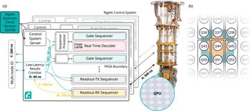
| 5 Управление | Электроника при комнатной температуре + коаксиальный / гибкий кабель на кубит · основная ▣ Fig. 1a (QPU + control system with FPGA decoder); Methods: Description of control system ✅ room-temperature RF control; Riverlane FPGA decoder in the loop, 9.6 µs total reaction for 9 rounds (6.5 µs decode + 3.1 µs communication) |
| 6 Считывание | Дисперсионное СВЧ-считывание (+TWPA, фильтр Парселла) · основная ▣ Fig. 1b (multiplexed readout feedlines to RX/TX cards); Fig. 1a (latency A–B) ✅ dispersive |
| 7 Код | Повёрнутый поверхностный код (+ yoked-варианты) · основная ▣ Fig. 2a (stability patch); Fig. 3a (logical error vs rounds) ✅ 8-qubit stability experiment on a rotated planar surface-code patch, real-time FPGA Collision Clustering decoding, no post-selection; logical error 28.1(1)% at 5 rounds → 20.5(1)% at 25 rounds |
| 8 Декодер | ПЛИС-декодеры реального времени (LCD, Deltaflow) · основная ▣ Fig. 3c–d (FPGA decode time at 156.25 MHz); Fig. 4 (response time); Methods: FPGA decoder integration ✅ Collision Clustering (union-find class) on FPGA, in loop; 0.44–0.79 µs per round at 156.25 MHz; 9.6 µs reaction for 9 rounds |
| 9 Межсоединение | |
| 10 Производство |
Стандартные рекорды
задержка декодирования за раунд → 440 ns · best in-loop for a non-Google superconducting machine (per round; range 0.44-0.79 us)
Jun 2026 · источник
задержка прямой связи → 9.6 µs · best measured superconducting reaction time (9 rounds)
6.5 us decode + 3.1 us communication · Jun 2026 · источник
источники: ✅ 7 / 10
Иллюстрации
У каждой иллюстрации — рассказ о том, что на ней, и строка авторства.