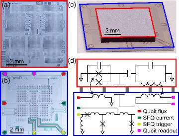
SEEQC SFQ-controlled 5-qubit system
SEEQC SFQ-controlled 5-qubit system
Профиль реестра — вариант архитектуры у этой машины (поля реестра — на английском)
тип кубита: transmon
механизм вентиля: no entangling gate published under SFQ control; single-qubit charge control by SFQ digital pulse trains
связность: not published
управление: Single Flux Quantum digital logic co-located with the qubits at 10 mK; integrated digital demultiplexing so several qubits share one control pathway; ~1 nW per qubit
размещение управления: SFQ at mK
считывание: dispersive
свидетельство вентиля: опубликованной цифры нет
флаги: 1q only
Технологии по слоям — ячейка машины на каждом слое
| 1 Носитель кубита | |
| 2 Кодирование | «Голый» физический кубит (без кодирования) · основная ◌ 🔎 Bare two-level subspace — Computational subspace of an anharmonic oscillator; leakage to |2⟩ is the price. |
| 3 Механизм вентиля | — undisclosed — есть, но не опубликовано ▣ Fig. S2 (2Q Gate Results); Supp. §I 2Q Calibration and Benchmarking ✅ no entangling gate published under SFQ control; single-qubit charge control by SFQ pulse trains, 1Q >99.5%, peaks >99.9% (Mar 2026) |
| 4 Связность / транспорт | Статическая решётка со связью ближайших соседей · основная ▤ Supp. §A Device Design and Fabrication (centre qubit capacitively coupled to 4 outer qubits); Fig. S1 (Experimental Diagram) ✅ connectivity not published; 5-qubit system |
| 5 Управление | Цифровое управление на БОК-логике (4 K / mK) · основная ▣ Fig. 1 (RT vs 4K cryo-CMOS vs integrated SFQ control); Fig. 3 (SFQ demultiplexer); Fig. S3 (SFQ Circuit Schematics); §Demultiplexer (DMX) Results; §Power Dissipation ✅ SFQ digital logic co-located with qubits at 10 mK; digital demultiplexing, <1 line per qubit; ~1 nW per qubit; no detectable quasiparticle poisoning (Mar 2026) |
| 6 Считывание | Дисперсионное СВЧ-считывание (+TWPA, фильтр Парселла) · основная ▤ Supp. §B Experimental Setup; Fig. S1 (Experimental Diagram) 🔎 dispersive; digital on-die readout is a stated next milestone |
| 7 Код | |
| 8 Декодер | |
| 9 Межсоединение | Многокристальная сборка в одном модуле (flip-chip, bump-bonding с управляющим кристаллом) · основная ▤ Supp. §A Device Design and Fabrication ✅ flip-chip: 5×5 mm quantum chip bump-bonded (indium on an Al hard stop, 10 µm gap) to a 10×10 mm carrier chip with all passive wiring and SFQ elements; signals couple across the vacuum gap |
| 10 Производство | Литография сверхпроводниковых кубитов (переходы Al/AlOx/Al, разводка из Nb, 300 mm) · основная ▤ Supp. §A Device Design and Fabrication (SEEQC SFQuClass Nb process, 1 kA/cm2 JJs, high-kinetic-inductance layer) ✅ |
Стандартные рекорды
линий управления на кубит → 1 lines/qubit · best (digital demultiplexing at mK; exact ratio not published)
power ~1e-9 W per qubit at mK · Mar 2026 · источник
источники: ✅ 6 / 10
Иллюстрации
У каждой иллюстрации — рассказ о том, что на ней, и строка авторства.